Member Detailing Settings
- General Overview
- Tips and Tricks
- Related Tools
Beams
Preferred bottom flange view style: ![]() Cross section or
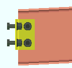
Cross section or ![]() Worm's eye view. This Beams section option applies when the bottom flange of a beam needs to be pictured on the beam's detail in order to show something that cannot be seen in another view. The choice made here sets which style of view will be generated. In member isolation. The view that is generated will be listed on the view list. Unless that view is deleted by the user, it will subsequently be regenerated on the beam's detail during Detail Members.
Worm's eye view. This Beams section option applies when the bottom flange of a beam needs to be pictured on the beam's detail in order to show something that cannot be seen in another view. The choice made here sets which style of view will be generated. In member isolation. The view that is generated will be listed on the view list. Unless that view is deleted by the user, it will subsequently be regenerated on the beam's detail during Detail Members.
|
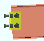
Cross section causes a BOTTOM FLANGE VIEW, CROSS SECTION to be generated if it is needed.
Also: You can change the view on an individual, member-by-member basis in member isolation. You can change the depth checking limits for preset views and system-generated member views in Home > Project Settings > Fabricator > Detailing > Member View Defaults.
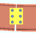
Show bottom flange on details if holes or materials detected there:  or
or  .
.
If this box is checked (
If the box is not checked (
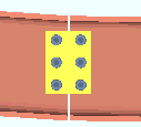
Show top flange on details if holes or materials detected there: or .
If this box is checked (
If the box is not checked (
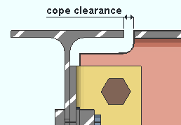
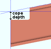
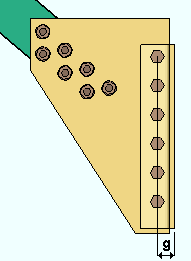
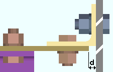
Provide minimum cope depth: ![]() or
or ![]() . This Beams section option applies to any beam with a designed copes when Provide minimum cope depth is set to Automatic under
. This Beams section option applies to any beam with a designed copes when Provide minimum cope depth is set to Automatic under ![]() Connection type
Connection type
|
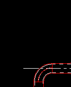
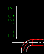
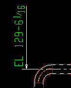
d = cope depth. Click here for special-case examples. |
If this box is checked (
If the box is not checked (
Other controls affecting cope depth: Minimum cope radius center clearance, Round cope depth to the nearest, Cope cut type
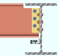
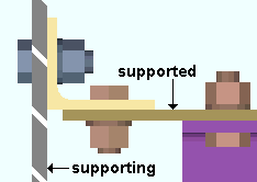
Minimum clearance for cope: The minimum distance you want connection design to apply for the clearance between the supporting beam's flange and the flange of the supported beam that is being coped.
Other controls affecting cope clearance: Round cope length to nearest
Minimum cope radius center clearance from face of flange: The minimum distance that the center of the cope must be located from the face of the flange.
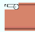
|
r = cope radius |
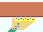
The clearance entered here applies when beams are coped. A "cope" is an L-shaped cut to the web and flange of a beam that prevents material interferences. Connection design applies the minimum clearance that is set here when, for example, it copes a supported beam so that it clears the supporting beam's flange.
Round cope length to nearest: The accuracy (0.1 to 2 inches imperial; 0 to 51 mm metric) to which you want the length of a cope measured. This Beams section option applies not just to beams, but also to any member or material with an end prep cope operation on it.
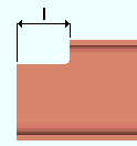
|
l = cope length. |
Effect on connection design: The accuracy that is entered here applies when connection design copes beams in order to prevent material interferences. Connection design rounds the length of the cope it generates up to the nearest multiple of the value set here. If a small number like 1/8 inch has been entered here, the cope is tighter than if a larger value such as 1/2 has been entered.
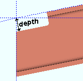
Round cope depth to nearest: The accuracy (0.1 to 2 inches imperial ; 0 to 51 mm metric) to which you want the depth of a cope measured.
|
|
d = cope depth. Click here for special-case examples. |
Effect on connection design: The accuracy that is entered here applies when connection design copes beams in order to prevent material interferences. Connection design rounds the depth of the cope it generates up to the nearest multiple of the value set here. If a small number like 1/8 inch has been entered here, the cope is tighter than if a larger value such as 1/2 has been entered.
Cope radius: The distance from the center of the cope to any point on the coped corner's circular edge. This sets the default curvature for cope corners on members with a Cope plain operation. You can override this default by setting a different Cope radius on the beam or other member type. This setup option also sets the default cope radius for Cope plain operations that are specified for miscellaneous members on the Rolled Section Material window.
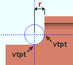
|
r = cope radius. Vertical and horizontal construction lines at the vertex points (vtpt) of the cope corner meet at the center point of a construction circle whose Radius is equal to the Cope radius. |
Cope cut type: Perpendicular to web angle (legacy) or Parallel to flange. This setup option applies not just to beams, but also to any member with a Cope plain operation. Connection design automatically copes beams, where necessary. Generally speaking, copes for member types other than beams need to be applied by the user. This option applies to both system-generated and user-added copes. If the Web cut angle on the member is 0, the member's web is perpendicular to its flange, and a Cope plain operation produces the same results, no matter what choice is selected here.
|
|
Perpendicular to web angle (legacy) makes the cope's length perpendicular to the Web cut angle. The Depth of a cope is measured parallel with the Web cut angle.
Parallel to flange makes the cope's length parallel to the flange (top flange for a top flange operation). The Depth of the cope is measured perpendicular to the flange.
Round off material length where possible: ![]() or
or ![]() . This Beams section option applies to the connection design for any beam with a clip angle or bent plate on its right end in a beam-to-beam or beam-to-column framing situation.
. This Beams section option applies to the connection design for any beam with a clip angle or bent plate on its right end in a beam-to-beam or beam-to-column framing situation.
|
gap = clearance that is changed. Connection design decreases or increases this gap when it rounds the length of the beam's main material up or down to the nearest 1/4 inch. |
If this box is checked (
If the box is not checked (
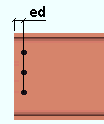
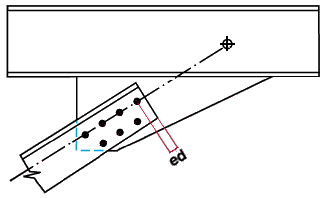
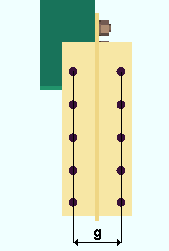
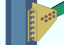
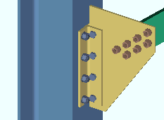
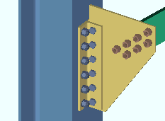
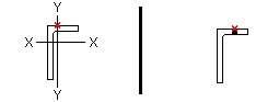
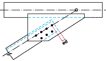
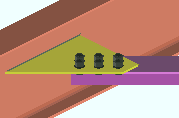
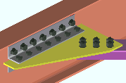
Member end edge distance: The distance from the edge of the beam to the center of the first column of holes. This dimension is measured parallel with the member line of the beam.
|
ed = edge distance. |
Square cut ends of sloped beams: ![]() or
or ![]() . This Beams section option applies, when checked, to the end of a sloping beam with a clip angle, single-plate shear, shear through plate, or bent plate connection. The option, when checked, can also apply to a slightly sloping column with a hanger connection.
. This Beams section option applies, when checked, to the end of a sloping beam with a clip angle, single-plate shear, shear through plate, or bent plate connection. The option, when checked, can also apply to a slightly sloping column with a hanger connection.
|
|
If this box is checked (
Also see: Checking the box for Skew holes in plate on a single-plate shear connection (shear tab) or for Skew holes in angle for clip angles bolted to a beam web allows connection design to square cut beams that are at greater slopes.
If the box is not checked (
Square cut ends for spliced beam connection: ![]() or
or ![]() . This Beams section option applies to Non-moment splice plates on beams at different slopes.
. This Beams section option applies to Non-moment splice plates on beams at different slopes.
|
|
If this box is checked (
If the box is not checked (
Detailed: ![]() In position or
In position or ![]() Horizontal. This Beams section option applies to beams when you Detail Members.
Horizontal. This Beams section option applies to beams when you Detail Members.
|
|
If
If
Altering a member's main view: In Member Isolation
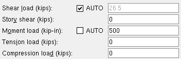
Show design loads on details: ![]() None or
None or ![]() Input or
Input or ![]() All. This Beams section option applies to beams whose piecemarks you select when you Detail Members. If Input or All is selected, you can additionally choose to Show member quantities and/or Show member numbers.
All. This Beams section option applies to beams whose piecemarks you select when you Detail Members. If Input or All is selected, you can additionally choose to Show member quantities and/or Show member numbers.
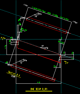
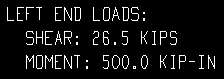
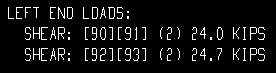
| Loads on the left end, Beam Edit window: | |
|
|
| Input loads on the beam detail, left end: | |

|
|
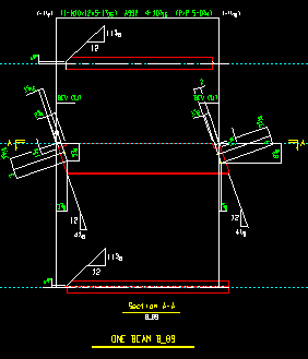
| All loads on the beam detail, left end: | |
|
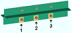
| Each of these examples is from a detail of four beams combined under the same piecemark. Two of the beams -- member numbers [90] and [91] -- have a user input Shear load of 24.0 kips. The other two beams -- [92] and [93] -- have an automatically calculated Shear load of 24.7 kips. | ||
|
Example 1: Show design loads ... is Input. |
|
|
Example 2: Show design loads ... is All. |
|
|
Example 3: Show design loads ... is All. |
|


Show capacity loads on details: ![]() None or
None or ![]() All. This Beams section option applies to beams whose piecemarks you select when you Detail Members. The capacity loads reported on the beam detail should match the Connection Design Calculations or Expanded Connection Design Calculations so long as everything -- the design calculations, the model, the detail -- is all up to date.
All. This Beams section option applies to beams whose piecemarks you select when you Detail Members. The capacity loads reported on the beam detail should match the Connection Design Calculations or Expanded Connection Design Calculations so long as everything -- the design calculations, the model, the detail -- is all up to date.
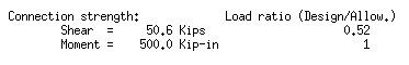
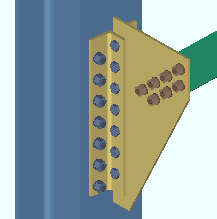
| Connection capacity loads (Calcs): |
|
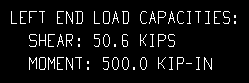
| Show capacity loads on details = All: |
|
Theoretically, if the beam has a system piecemark. corresponding end connections for all beams that share that same piecemark should all have the same capacity.
The
Show grid notes on details: ![]() None or
None or ![]() One or
One or ![]() All. This Beams section option applies to beams that you select when you Detail Members.
All. This Beams section option applies to beams that you select when you Detail Members.
|
|
Show end elevations on details: ![]() None or
None or ![]() First or
First or ![]() All. This Beams section option applies to beams whose piecemarks you select when you Detail Members.
All. This Beams section option applies to beams whose piecemarks you select when you Detail Members.
None
|
First
|
All
 |
If
If
If
End elevation reference point: ![]() Material end or
Material end or ![]() Work point. This Beams section option applies when you Detail Members. On details of non-sloping beams, the same elevations are reported regardless of the choice made here.
Work point. This Beams section option applies when you Detail Members. On details of non-sloping beams, the same elevations are reported regardless of the choice made here.
Material end
|
Work point
|
Select
Select
Add work point dimensions: ![]() or
or ![]() . When you Detail Members the option selected here applies to details of sloping beams if Work Point is selected for End elevation reference point.
. When you Detail Members the option selected here applies to details of sloping beams if Work Point is selected for End elevation reference point.
 |
 |
If this box is checked (
If the box is not checked (
Show camber on the bill of material: ![]() or
or ![]() . This Beams section option applies to the bills of material that are generated when you Detail beams with camber.
. This Beams section option applies to the bills of material that are generated when you Detail beams with camber.
| Entry made here, in Fabricator Setup: |
|
|
| Camber annotation on Beam Edit window: |
|
|
| Camber in the Remarks column on the bill: |
|
If this box is checked (
Exception: If 0 is entered as the Mid-ordinate on the Beam Edit window, camber is not shown in the bill of material.
Also: The Rolling operation must be set to Camber annotation or to Camber (Both).If the box is not checked (
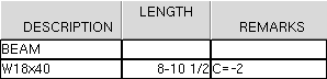
In the example above: The characters entered here are C =. The Mid-ordinate is -2. Therefore, the annotation in the Remarks column of the bill of material is C=-2.
Other ways to show camber: You can Show camber on members on erection view drawings or display Camber annotations in 3D Modeling views.
Columns
Preferred baseplate view orientation: ![]() Bird's eye view or
Bird's eye view or ![]() Worm's eye view.
Worm's eye view.
| Bird's eye view: | ||||||
|
||||||
| Worm's eye view: | ||||||
|
Also: In Modeling, if you select a column with a base plate or other bottom-end-of-column item that needs to be depicted on its detail, then Mark Member for Processing > then Process and Create Solids > then Isolate Member by Location, the resulting view that is shown of that selected column in member isolation will have the Preferred baseplate view orientation that is selected here. If you then select that same column for Detail Members, the Preferred baseplate view orientation that is selected here will be shown on the column detail.
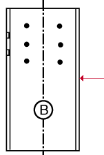
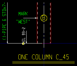
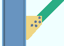
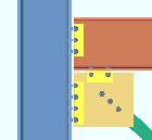
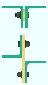
Show C-face on details: ![]() As required or
As required or ![]() Always or
Always or ![]() Never. On a wide flange or tube column detail, face B is web near side. Face C is the flange on the right when you are looking at face B.
Never. On a wide flange or tube column detail, face B is web near side. Face C is the flange on the right when you are looking at face B.
|
face C |
Also: Process and Create Solids results in the choice made here being applied to member isolation. If FACE C View is shown in the view list in member isolation, then Detail Members draws that face C view on the column detail.
Show if holes or materials detected there (C-face): or .
If this box is checked (
If the box is not checked (
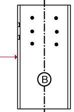
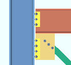
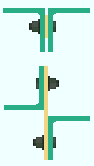
Show A-face on details: ![]() As required or
As required or ![]() Always or
Always or ![]() Never. On a wide flange or tube column detail, face B is web near side. Face A is the left flange when you are looking at face B.
Never. On a wide flange or tube column detail, face B is web near side. Face A is the left flange when you are looking at face B.
| face A |
|
Also: Process and Create Solids results in the choice made here being applied to member isolation. If FACE A View is shown in the view list in member isolation, then Detail Members draws that face A view on the column detail.
Show if holes or materials detected there (A-face): or .
If this box is checked (
If the box is not checked (
Annotate faces of pipe on details: ![]() or
or ![]() . This Columns section option applies to the details of any HSS round (pipe) columns whose piecemarks you select when you Detail Members.
. This Columns section option applies to the details of any HSS round (pipe) columns whose piecemarks you select when you Detail Members.
 |
 |
If this box is checked (
If the box is not checked (
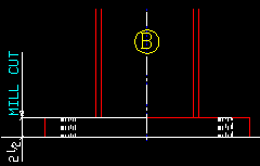
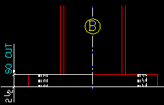
Mill cut column ends: ![]() or
or ![]() . This affects labeling only. It applies to the details of any columns whose piecemarks you select when you Detail Members.
. This affects labeling only. It applies to the details of any columns whose piecemarks you select when you Detail Members.
 |
 |
If this box is checked (
If the box is not checked (
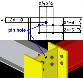
Show erection pin holes: ![]() or
or ![]() . This option adds an erection pin hole to the column when Erection pin hole is set to Automatic under
. This option adds an erection pin hole to the column when Erection pin hole is set to Automatic under ![]() General settings
General settings
|
Connection design does not automatically create an erection pin hole in this situation since the pin hole interferes with the clip angle on the beam. To get a pin hole, the user has to select Yes instead of Automatic on the Column Edit window. |
If this box is checked (
Exception: A pin hole is not automatically designed if it interferes with a connection to the column.
If the box is not checked (
Erection pin holes are CNC downloadable:
Erection pin hole location for flange plated splice connection:
Erection pin hole diameter: The erection pin hole diameter. This applies to columns that subsequently undergo Process and Create Solids.
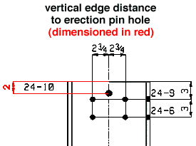
Vertical edge distance of hole: The distance from the top edge of the column to the center of the first row of holes. This applies to columns that subsequently undergo Process and Create Solids.
Detailed: ![]() In position or
In position or ![]() Vertical or
Vertical or ![]() Horizontal. This applies to columns when you Detail Members. For a perfectly vertical column, In position gives the same results as selecting Vertical.
Horizontal. This applies to columns when you Detail Members. For a perfectly vertical column, In position gives the same results as selecting Vertical.
In position
|
Vertical
|
Horizontal
|
If
If
If
Altering a member's main view: In Member Isolation.
Show design loads on details: ![]() None or
None or ![]() Input or
Input or ![]() All. This Columns section option applies to the columns whose piecemarks you select when you Detail Members. If Input or All is selected, you can additionally choose to Show member quantities and/or Show member numbers.
All. This Columns section option applies to the columns whose piecemarks you select when you Detail Members. If Input or All is selected, you can additionally choose to Show member quantities and/or Show member numbers.
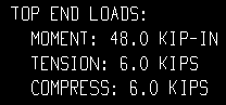
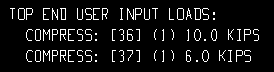
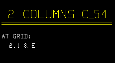
| Loads on the top end, Column Edit window: |
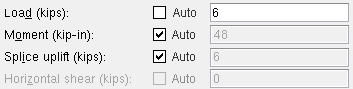
|
| Input top end loads on the column detail: |

|
| All top end loads on the column detail: |
|
| These examples are from a detail of two columns combined under the same piecemark. One column -- member number [36] -- has a user-input Load of 10.0 kips. The other column -- [37] -- has a user-input 6.0 kips. | ||
|
Example 1: Show design loads ... is Input. |
|
|
Example 2: Show design loads ... is All. |
|

Show capacity loads on details: ![]() None or
None or ![]() All. This applies to columns whose piecemarks you select when you Detail Members. The capacity loads reported on the column detail should match the Connection Design Calculations or Expanded Connection Design Calculations so long as the design calculations, the model, and the detail are up-to-date.
All. This applies to columns whose piecemarks you select when you Detail Members. The capacity loads reported on the column detail should match the Connection Design Calculations or Expanded Connection Design Calculations so long as the design calculations, the model, and the detail are up-to-date.
| Connection capacity loads (Calcs): |
|
|
| Show capacity loads on details = All: |

|
Theoretically, if the column has a system piecemark. corresponding end connections for all columns that share that same piecemark should all have the same capacity. This means that each connection capacity load that is reported will apply to the total quantity of members under the piecemark.
Show grid notes on details: ![]() None or
None or ![]() One or
One or ![]() All. This Columns section option applies to columns when you Detail Members.
All. This Columns section option applies to columns when you Detail Members.
One
|
All
|
Select
Select
Select
Show end elevations on details: ![]() None or
None or ![]() First. This Columns section option applies to columns when you Detail Members.
First. This Columns section option applies to columns when you Detail Members.
None
|
First
|
If
If
Top elevation reference point: ![]() Material end or
Material end or ![]() Work point. This Columns section option applies when you Detail Members and when First is selected for Show end elevations on details.
Work point. This Columns section option applies when you Detail Members and when First is selected for Show end elevations on details.
|
||
| The top end of a column's material may be different from its top-end work point when, for example, the column's work point is to the workline of a beam that is above the column. |
If
If
Show sections framing into column: ![]() or
or ![]() . This Columns section option applies to columns when you Detail Members.
. This Columns section option applies to columns when you Detail Members.
 |
 |
If this box is checked (
If the box is not checked (
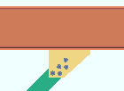
Column: Shear Through Plates
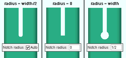
HSS notch radius: ![]() Auto or 0 or a radius. The radius is for the circular cutouts at the ends of the notch in an HSS column (pipe or tube) that is framed to by a beam (or two opposing beams) which have thru shear plate connections. The notch is generated for inserting the thru shear plate into.
Auto or 0 or a radius. The radius is for the circular cutouts at the ends of the notch in an HSS column (pipe or tube) that is framed to by a beam (or two opposing beams) which have thru shear plate connections. The notch is generated for inserting the thru shear plate into.
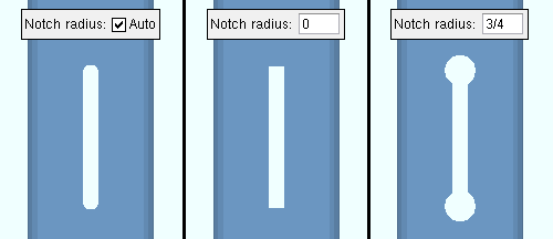
0 (with
a radius (with
Note 1: The circular cutout is automatically included as a hole in an SDS2 CNC file if, during the generation of that file, Add holes was set to in all radii in CNC Setup.
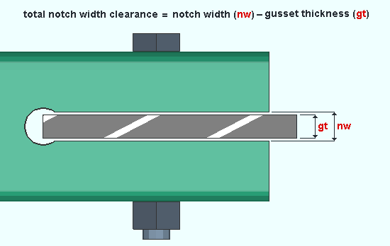
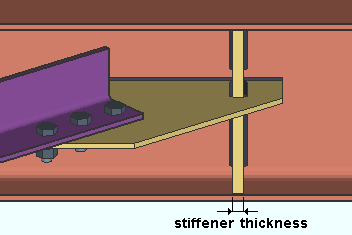
Note 2: The notch width is equal to the sum of the thickness of the shear through plate and the Total notch width clearance that is entered below.
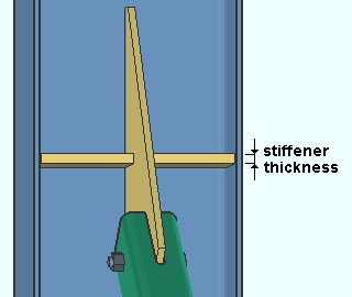
Total notch width clearance: The clearance for the shear through plate that is inserted into a notch in an HSS (pipe or tube) column.
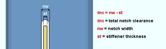
|
| Total notch width clearance is equal to the notch width minus the stiffener thickness. |
Effect on connection design: The entry made here controls the Notch width that connection design creates in the column that a shear through plate frames through. A shear through plate can be designed for beam-to-HSS-column framing situations when the beam's Input connection type is Shear or Auto standard or User Defined and
is set to Through plate or Split plate under . Connection design first determines the thickness and other dimensions of the through plate, then uses the Total notch width clearance to calculate the required notch size. HSS notch radius (above) also affects the design of the notch. Connection specifications
To override this setup option: Notch width (column end prep option for HSS sections).
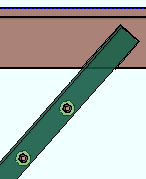
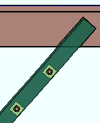
Vertical Braces
Locate angle braces on neutral axis: ![]() or
or ![]() . This Vertical Braces section option applies to vertical braces with angle material entered as the Section size when Locate on neutral axis is set to Automatic under
. This Vertical Braces section option applies to vertical braces with angle material entered as the Section size when Locate on neutral axis is set to Automatic under ![]() General settings
General settings
|
workline (x)
on neutral axis |
workline (x)
on gage line |
 |
|
If this box is checked (
If the box is not checked (
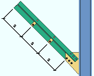
Minimum member end edge distance: The distance parallel with the workline of the vertical brace from the edge of the brace to the center of the nearest hole.
|
ed = edge distance for a vertical brace. |
Note: If you enter an extremely low edge distance (for example, 1/8 inch), connection design bases the minimum edge distance on the bolt diameter.
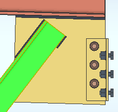
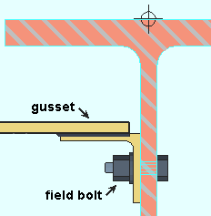
Gusset to supporting member: ![]() Welded or
Welded or ![]() Clip angle. This Vertical Braces section option applies in the following framing situations when Gusset to supporting member is set to Automatic under
Clip angle. This Vertical Braces section option applies in the following framing situations when Gusset to supporting member is set to Automatic under ![]() Connection specifications
Connection specifications
| |
|
|
| Case 1: vertical brace to beam only |
|
|
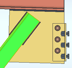
| Case 2: vertical brace to column only |
|

|
| Case 3: beam on a vbrc to beam & column when a clip angle bolts to the column |
|
|
| Case 4: vertical brace to a wide flange vertical brace |

|

|
Detailed: ![]() In position or
In position or ![]() Horizontal. This Vertical Braces section option applies to vertical braces when you Detail Members.
Horizontal. This Vertical Braces section option applies to vertical braces when you Detail Members.
In position
|
Horizontal
|
If
If
Altering a member's main view: In Member Isolation
Show design loads on details: ![]() None or
None or ![]() Input or
Input or ![]() All. This Vertical Braces section option applies to vertical braces whose piecemarks you select when you Detail Members. If Input or All is selected, you can additionally choose to Show member quantities and/or Show member numbers.
All. This Vertical Braces section option applies to vertical braces whose piecemarks you select when you Detail Members. If Input or All is selected, you can additionally choose to Show member quantities and/or Show member numbers.
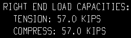
| Loads on the right end, Vertical Brace Edit window: |
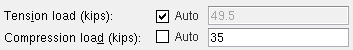
|
| Input loads on the vertical brace detail, right end: |

|
| All loads on the vertical brace detail, right end: |
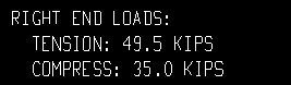
|
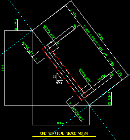
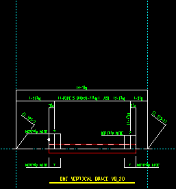
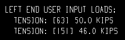
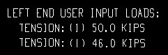
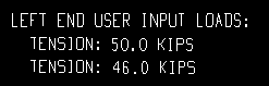
| Each of these examples is from a detail of two vertical braces combined under the same piecemark. One brace -- member number [63] -- has a user-input Tension load of 50.0 kips. The other brace -- [151] -- has a user-input Tension load of 46.0 kips. | ||
|
Example 1: Show design loads ... is Input. |
|
|
Example 2: Show design loads ... is Input. |
|
|
Example 3: Show design loads ... is Input. |
|
Show capacity loads on details: ![]() None or
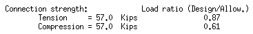
None or ![]() All. This Vertical Braces section option applies to vertical braces whose piecemarks you select when you Detail Members. The capacity loads shown on the vertical brace detail should match the capacity shown in the Connection Design Calculations or Expanded Connection Design Calculations so long as the design calculations, model, and detail are up to date.
All. This Vertical Braces section option applies to vertical braces whose piecemarks you select when you Detail Members. The capacity loads shown on the vertical brace detail should match the capacity shown in the Connection Design Calculations or Expanded Connection Design Calculations so long as the design calculations, model, and detail are up to date.
| Connection capacity loads (Calcs): |
|
| Show capacity loads on details = All: |
|
Theoretically, if the vertical brace has a system piecemark, corresponding end connections for all vertical braces that share that same piecemark should all have the same capacity. This means that each capacity load that is reported on the detail will apply to the total quantity of members under the piecemark.
Show grid notes on details: ![]() None or
None or ![]() One or
One or ![]() All. This Vertical Braces section option applies to vertical braces that you select when you Detail Members.
All. This Vertical Braces section option applies to vertical braces that you select when you Detail Members.
One
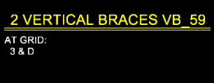
|
All
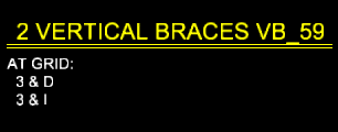
|
Show end elevations at workpoints on details: ![]() or
or ![]() . This Vertical Braces section option applies to vertical braces that you select when you Detail Members.
. This Vertical Braces section option applies to vertical braces that you select when you Detail Members.
|
|
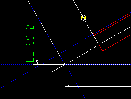
If this box is checked (
If the box is not checked (
HSS erection bolts: None or One or Two. This Vertical Braces section option applies when Automatic is selected for Erection bolts in ![]() Connection specifications
Connection specifications
|
|
|


None stops holes for erection bolts from being generated in the pipe or tube vertical brace.
One specifies that connection design generate a field erection bolt along with holes for inserting the bolt into.
Two instructs connection design to generate two field erection bolts along with holes for inserting the bolts into.
Bolt Settings (setup): HSS welded brace erection bolts
Spacing for two erection bolts: Hole spacing along brace (vbrc to beam)
Spacing for two erection bolts: Hole spacing along brace (vbrc to columns)
Spacing for two erection bolts: Hole spacing along brace (vbrc to beam & column)
Spacing for two erection bolts: Hole spacing along brace (vbrc, 2 point, to a beam)
Spacing for two erection bolts: Hole spacing along brace (vbrc, 2 point, to a column)
Hole type for HSS erection bolts: Standard round or Short slot or Long slot or Oversized round or User slot #1 or User slot #2. This Vertical Braces section option applies to the gusset (not the brace) when HSS erection bolts has been set to One or Two.

Effect on connection design: The hole type selected here applies to the holes in the gusset only. The holes in the brace are always standard round. Erection bolts may be designed on a HSS/pipe/tube vertical brace that is field welded to the gusset.
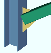
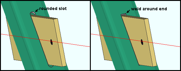
Intersection gusset notch preparation: Rounded slot or Weld around end. This Vertical Braces section option applies to vertical brace intersection plates for X bracing when the supporting vertical brace is a HSS (pipe or tube). The supporting vertical brace in X bracing is the brace that the supported vertical braces frame to. The intersection plate shop welds to this brace.
|
| When two vertical braces frame to opposite sides of an HSS brace, NS and FS notches are created for inserting the intersection plate into. |
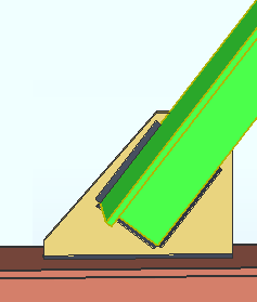
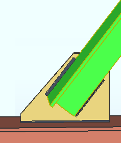
Rounded slot instructs connection design to create NS and FS notches with rounded ends. The entry made to HSS notch radius and Total notch clearance controls the rounding.
Weld around end instructs connection design to create NS and FS notches with squared ends. The Total notch clearance controls how tightly the notch is fit around the intersection plate.
HSS notch radius: ![]() Auto or 0 or a radius. This sets the radius of the circular cutout at the interior end of the notch at the end of an HSS (pipe or tube) vertical brace. The notch is generated for inserting the gusset plate into. A hole at the end of the notch can be generated with a CNC machine to make fabrication of the notch easier. This also applies to intersection gusset plates when Rounded slot is selected.
Auto or 0 or a radius. This sets the radius of the circular cutout at the interior end of the notch at the end of an HSS (pipe or tube) vertical brace. The notch is generated for inserting the gusset plate into. A hole at the end of the notch can be generated with a CNC machine to make fabrication of the notch easier. This also applies to intersection gusset plates when Rounded slot is selected.
|
In these examples, the notch width is 1/2 inch. |
0 (with
a radius (with
Note: The circular cutout is automatically included as a hole in an SDS2 CNC file if, during the generation of that file, Add holes was set to in all radii in CNC Setup.
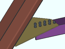
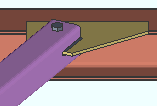
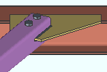
Total notch width clearance: The clearance for a gusset plate that is inserted into the notch in an HSS section when the Pipe/tube end-fitting is Welded. When the Pipe/tube end-fitting is Paddle plate, this is the clearance between the paddle plate and the notch in the HSS section. When the Connection arrangement for a wide flange vertical brace is Paddle plates, this is the clearance between the gusset and the notch in the paddle plate. Connection design uses the clearance that is entered here to determine the Notch width in the HSS section or, for a wide flange vertical brace paddle plate connection, the notch width in the paddle plate.
|
| This example shows a connection like you would get when Pipe/tube end-fitting is Welded. As stated above, the Total notch width clearance also applies to other types of connections. |
To override this setup option: Notch width (end prep option for HSS sections)
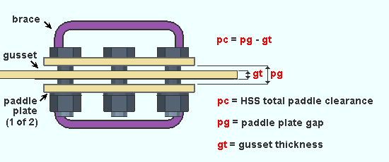
HSS double paddle clearance: The clearance for the gusset plate that is sandwiched between the double paddle plates in a vertical brace's double paddle plate connection.
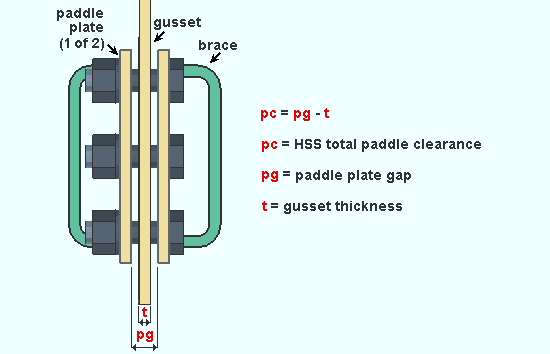
|
| HSS double paddle clearance is equal to the paddle plate gap minus the gusset thickness. |
Effect on connection design: The entry made here controls the spacing between the double paddle plates that connection design creates when Double paddle plate has been selected as a vertical brace's Pipe/tube end fitting.
Welded angle end weld: ![]() or
or ![]() . This Vertical Braces section option applies when Automatic is selected for Include end welds under
. This Vertical Braces section option applies when Automatic is selected for Include end welds under ![]() Connection specifications
Connection specifications
|
|
If this box is checked (
If the box is not checked (
Welded angle balanced welds: This Vertical Braces section option applies when Automatic is selected for Balanced welds under ![]() Connection specifications
Connection specifications
|
|
If this box is checked (
If the box is not checked (
Maximum web stiffener thickness: The maximum thickness of stiffeners for vertical brace gusset plates that weld to a beam's web.
|
Connection design may create stiffeners for a vertical brace gusset plate to a beam's web when Check supporting member web stress is set to As required in the vertical brace's |
Avoiding connection failure: A vertical brace gusset plate connection may fail with the message Supporting web/flg overstressed by axial load if the Maximum web stiffener thickness that is entered here is too low.
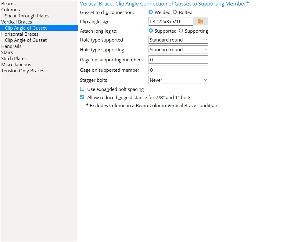
Vertical Braces: Clip Angle of Gusset to Supporting Member*
* Excludes the clip angle to a column in a beam-column-vertical brace condition.
Gusset to clip connection: ![]() Welded or
Welded or ![]() Bolted. This Vertical Braces section option applies in the above-listed framing situations when Gusset to clip connection is set to Automatic under
Bolted. This Vertical Braces section option applies in the above-listed framing situations when Gusset to clip connection is set to Automatic under ![]() Connection specifications
Connection specifications
|
|
Clip angle size: The angle section size (angle) to be used for both the near side and far side gusset clip angles when Clip angle size is set to ![]() Auto on the Vertical Brace Edit window (or for a user defined connection) in the above-listed framing situations.
Auto on the Vertical Brace Edit window (or for a user defined connection) in the above-listed framing situations.
The angle you enter here must exist in the local shape file, or validation does not accept your entry. To enter an angle section size, you can type in the section size that you want (for example, L4x3x5/16), or you can press the file cabinet browse button
( and double-click any section size that is on the list of available angles in the local shape file.)
How connection design applies this angle: If connection design determines that the angle will work in the connection, the angle is used. If it doesn't work, connection design tries to select an angle from the miscellaneous Preferred Angle Sizes setup list. If none of those angles work, connection design chooses an angle from the local shape file.
Attach long leg to: ![]() Supported or
Supported or ![]() Supporting. This Vertical Braces section option applies to vertical brace gusset clip angles when Attach long leg to is set to Automatic under
Supporting. This Vertical Braces section option applies to vertical brace gusset clip angles when Attach long leg to is set to Automatic under ![]() Connection specifications
Connection specifications
|
In this example, the long leg of each of the gusset clip angles bolts to the column since Attach long leg to is set to Supporting. |
Hole type supported: Standard round or Short slot or Long slot or Oversized or User slot #1 or User slot #2. This is the hole type for shop bolting the leg of the clip angle to the vertical brace gusset plate when Hole type supported is set to ![]() Auto
Auto
Hole type supporting: Standard round or Short slot or Long slot or Oversized or User slot #1 or User slot #2. This is the hole type for field bolting the outstanding leg of the angle to the supporting beam, column or wide flange vertical brace when Hole type supporting is set to ![]() Auto
Auto
Gage on supporting member: 0 (zero) or the center-to-center distance between columns of holes on the outstanding legs of the clip angles. This Vertical Braces section option applies when Gage on supporting is set to ![]() Auto
Auto
|
g = gage on supporting member. The supporting member in this example is a column (not shown). Connection design uses double clip angles for vertical braces to the supporting member. |
0 (zero) instructs connection design to treat all situations as exceptions (see below).
A specific center-to-center distance instructs connection design to attempt to use this gage.
Exceptions: If this gage doesn't work, then connection design uses the gage in the local shape file for the supporting member (for example, Flange gage for a wide flange column). If that gage doesn't work, connection design uses the angle gage.
Gage on supported member: The GOL (gage on leg) as measured from the corner of the angle to the first hole in the leg to the gusset. This gage applies to the Clip angle size that is selected above or to the Clip angle size selected on the Vertical Brace Edit window (or for a user defined connection) as long as it is greater than or equal to the Minimum edge distance for the bolt size used plus the 1/2-inch (13 mm) clearance between the gusset and the supporting member.
|
g = gage on supported member. The supported member is the vertical brace. |
Tip: Entering 0 (zero) instructs connection design to use the Minimum edge distance for the bolt size used plus the 1/2-inch clearance between the gusset and the supporting member.
Stagger bolts: ![]() or
or ![]() . This Vertical Braces section option applies when Automatic is selected for Stagger bolts under
. This Vertical Braces section option applies when Automatic is selected for Stagger bolts under ![]() Connection specifications
Connection specifications
|
|
If this box is checked (
If the box is not checked (
Use expanded bolt spacing: ![]() or
or ![]() . This Vertical Braces section option applies regardless of the Clip angle size that is selected on the Vertical Brace Edit window (or for a user defined connection).
. This Vertical Braces section option applies regardless of the Clip angle size that is selected on the Vertical Brace Edit window (or for a user defined connection).
 |
 |
If this box is checked (
If the box is not checked (
Allow reduced edge distance for 7/8" and 1" bolts: ![]() or
or ![]() . For metric bolts, This Vertical Braces section option applies to bolts with diameters of 20 mm, 22 mm and 24 mm. It applies to the design of clip angles for attaching the gusset of a vertical brace to a supporting member other than a column in a beam-column-vertical brace condition.
. For metric bolts, This Vertical Braces section option applies to bolts with diameters of 20 mm, 22 mm and 24 mm. It applies to the design of clip angles for attaching the gusset of a vertical brace to a supporting member other than a column in a beam-column-vertical brace condition.
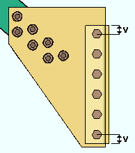
|
v = edge distance |
If this box is checked (
If the box is not checked (
Also: Bolt diameter sets the diameter of bolts for vertical brace gusset clips.
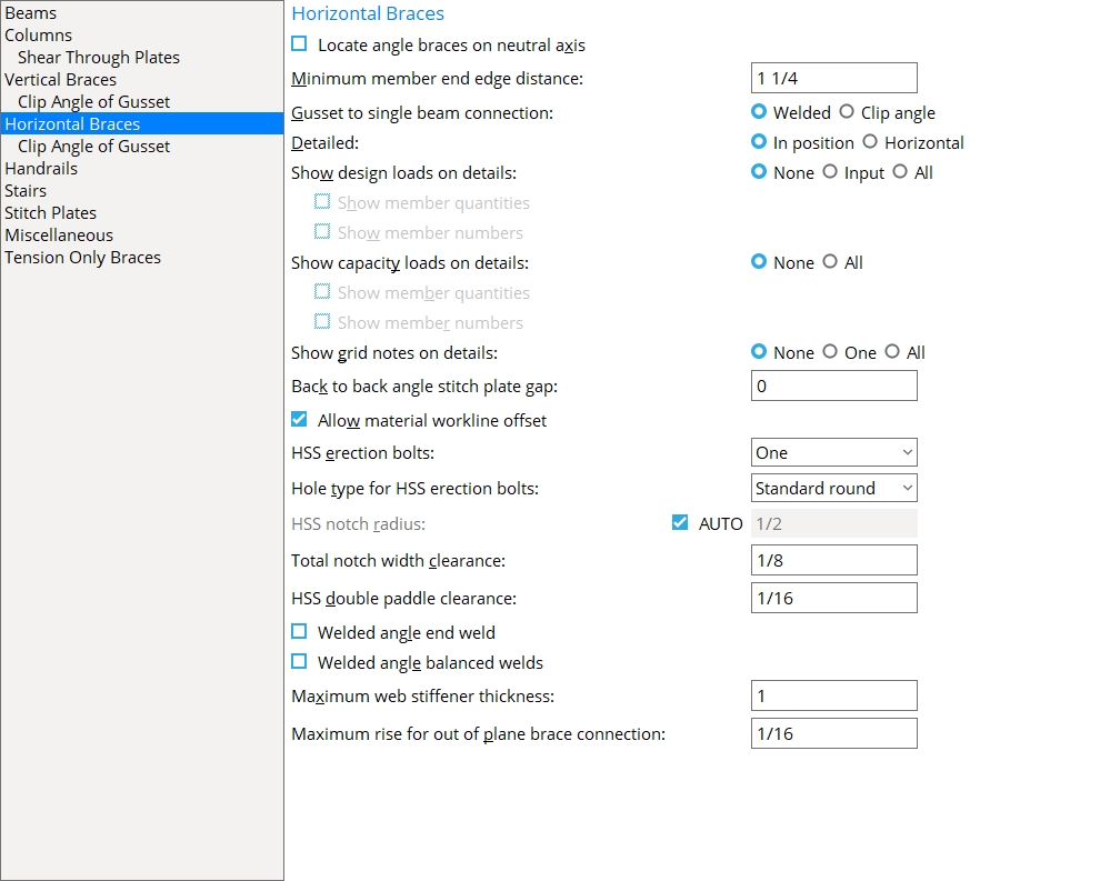
Horizontal Braces
Locate angle braces on neutral axis: ![]() or
or ![]() . This Horizontal Braces section option applies to horizontal braces with angle material entered as the Section size when Locate on neutral axis is set to Automatic under
. This Horizontal Braces section option applies to horizontal braces with angle material entered as the Section size when Locate on neutral axis is set to Automatic under ![]() General settings
General settings
|
workline (x)
on neutral axis |
workline (x)
on gage line |
|
|
If this box is checked (
If the box is not checked (
Minimum member end edge distance: The distance parallel with the workline of the horizontal brace from the edge of the brace to the center of the nearest hole.
|
ed = edge distance for a horizontal brace. |
Note: If you enter an extremely low edge distance (for example, 1/8 inch), connection design calculates the minimum edge distance based on the bolt diameter.
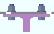
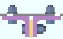
Gusset to single beam connection: ![]() Welded or
Welded or ![]() Clip angle. This Horizontal Braces section option applies to a horizontal brace framing to a single beam when Gusset to beam connection is set to Automatic under
Clip angle. This Horizontal Braces section option applies to a horizontal brace framing to a single beam when Gusset to beam connection is set to Automatic under ![]() Connection specifications.
Connection specifications.
|
|
Also see: Gusset to beam clips (Bolted or Welded) and Gusset clips on (Both sides or Near side or Far side).
Detailed: ![]() In position or
In position or ![]() Horizontal. This Horizontal Braces section option applies to horizontal braces when you Detail Members. In member isolation, the main view of the brace is always horizontal.
Horizontal. This Horizontal Braces section option applies to horizontal braces when you Detail Members. In member isolation, the main view of the brace is always horizontal.
In position
|
Horizontal
|
If
If
Altering a member's main view: In Member Isolation
Show design loads on details: ![]() None or
None or ![]() Input or
Input or ![]() All. This Horizontal Braces section option applies to horizontal braces that are selected when you Detail Members. If Input or All is selected, you can additionally choose to Show member quantities and/or Show member numbers.
All. This Horizontal Braces section option applies to horizontal braces that are selected when you Detail Members. If Input or All is selected, you can additionally choose to Show member quantities and/or Show member numbers.
| Loads on the left end, Horizontal Brace Edit window: |
|
|
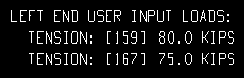
| Input loads on the horizontal brace detail, left end: |

|
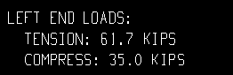
| All loads on the horizontal brace detail, left end: |
|
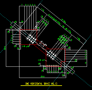
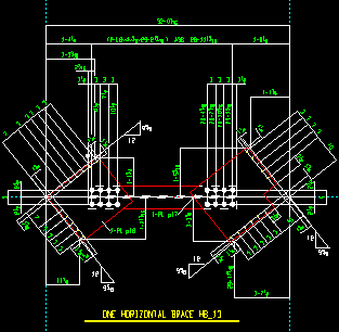
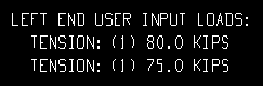
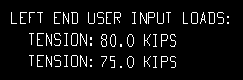
Each of these examples is from a detail of two horizontal braces combined under the same piecemark. One brace -- member number [159] -- has a user-input Tension load of 80.0 kips. The other brace -- [167] -- has a user-input Tension load of 75.0 kips.
Example 1: Show design loads ... is Input. and .
Example 2: Show design loads ... is Input. and .
Example 3: Show design loads ... is Input. and .
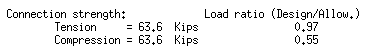
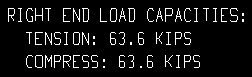
Show capacity loads on details: ![]() None or
None or ![]() All. This Horizontal Braces section option applies when Show design loads on details is set to Input or All and you subsequently Detail Members (horizontal braces). The capacity loads shown on the horizontal brace detail should match the capacity shown in the Connection Design Calculations or Expanded Connection Design Calculations so long as everything -- the design calculations, the model, the detail -- is all up to date.
All. This Horizontal Braces section option applies when Show design loads on details is set to Input or All and you subsequently Detail Members (horizontal braces). The capacity loads shown on the horizontal brace detail should match the capacity shown in the Connection Design Calculations or Expanded Connection Design Calculations so long as everything -- the design calculations, the model, the detail -- is all up to date.
| Connection capacity loads (Calcs): |
|
| Show capacity loads on details = All: |
|
Theoretically, if the horizontal brace has a system piecemark, corresponding end connections for all horizontal braces that share that same piecemark should all have the same capacity. This means that each connection capacity load that is reported on the detail will, theoretically, apply to the total quantity of members under the piecemark.
Show grid notes on details: ![]() None or
None or ![]() One or
One or ![]() All. This Horizontal Braces section option applies to horizontal braces that you select when you Detail Members.
All. This Horizontal Braces section option applies to horizontal braces that you select when you Detail Members.
One
|
All
|
Back to back angle stitch plate gap: The clearance that you want applied between the two "backs" of a back-to-back double-angle horizontal brace when Stitch plate gap is set to ![]() Auto
Auto
|
||
| A gap of 0 (zero) results in the back-to-back double-angle braces being designed without a stitch plate. |
Allow material workline offset: ![]() or
or ![]() . This Horizontal Braces section option applies when Automatic is selected for Allow material workline offset under
. This Horizontal Braces section option applies when Automatic is selected for Allow material workline offset under ![]() General settings
General settings
|
A material workline offset is allowed when a horizontal brace frames to the bottom flange of a beam. To get a connection in such a situation, the beam workline must be in the same plane as the beam's bottom flange. |
If this box is checked (
If the box is not checked (
HSS erection bolts: None or One or Two. This Horizontal Braces section option applies when Automatic is selected for Erection bolts under ![]() Connection specifications. Erection bolts may be designed on a HSS/pipe/tube horizontal brace that is field welded to the gusset.
Connection specifications. Erection bolts may be designed on a HSS/pipe/tube horizontal brace that is field welded to the gusset.

|
|
|
None specifies that connection design not generate an erection bolt or design holes into the pipe or tube horizontal brace.
One instructs connection design to generate a field erection bolt along with holes for inserting the bolt into.
Two configures connection design to generate two field erection bolts along with holes for inserting the bolts into.
Bolt Settings (setup): HSS welded brace erection bolts
Hole type for HSS erection bolts: Standard round or Short slot or Long slot or Oversized round or User slot #1 or User slot #2. This Horizontal Braces section option applies to the gusset (not the brace) when HSS erection bolts has been set to One or Two.
Effect on connection design: The hole type selected here applies to the holes in the gusset only. The holes in the brace are always standard round. Erection bolts may be designed on a HSS/pipe/tube horizontal brace that is field welded to the gusset.
HSS notch radius: ![]() Auto or 0 or a radius. This sets the radius of the circular cutout at the interior end of the notch at the end of an HSS horizontal brace. The notch is generated for inserting the gusset plate into. A hole at the end of the notch can be generated with a CNC machine to make fabrication of the notch easier.
Auto or 0 or a radius. This sets the radius of the circular cutout at the interior end of the notch at the end of an HSS horizontal brace. The notch is generated for inserting the gusset plate into. A hole at the end of the notch can be generated with a CNC machine to make fabrication of the notch easier.
|
|
In these examples, the notch width is 1/2 inch. |
0 (with
a radius (with
Note 1: This setting does not apply to intersecting gusset plates.
Note 2: The circular cutout is automatically included as a hole in an SDS2 CNC file if, during the generation of that file, Add holes was set to in all radii in CNC Setup.
Total notch width clearance: The clearance for a gusset plate that is inserted into the notch in an HSS section when the Pipe/tube end-fitting is Welded. When the Pipe/tube end-fitting is Paddle plate, this is the clearance between the paddle plate and the notch in the HSS section. Connection design uses the clearance that is entered here to determine the Notch width in the HSS section.
|
|
To override this setup option: Notch width (end prep option for HSS sections)
HSS double paddle clearance: The clearance for the gusset plate that is sandwiched between the double paddle plates in a horizontal brace's double paddle plate connection.
|
| HSS double paddle clearance is equal to the paddle plate gap minus the gusset thickness. |
Effect on connection design: The entry made here controls the spacing between the double paddle plates that connection design creates when Double paddle plate has been selected as a horizontal brace's Pipe/tube end fitting.
Welded angle end weld: ![]() or
or ![]() . This Horizontal Braces section option applies when Automatic is selected for Include end welds under
. This Horizontal Braces section option applies when Automatic is selected for Include end welds under ![]() Connection specifications
Connection specifications
|
|
If this box is checked (
If the box is not checked (
Welded angle balanced welds: This Horizontal Braces section option applies when Automatic is selected for Balanced welds under ![]() Connection specifications.
Connection specifications.
|
|
If this box is checked (
If the box is not checked (
Maximum web stiffener thickness: The maximum thickness of stiffeners for horizontal brace gusset plates that weld to a beam's web.
|
Connection design may create stiffeners for a horizontal brace gusset plate to a beam's web when Check supporting member web stress is set to As required in the horizontal brace's |
Avoiding connection failure: A horizontal brace gusset plate connection may fail with the message Supporting web/flg overstressed by axial load if the Maximum web stiffener thickness that is entered here is insufficient to stiffen the web.
Maximum rise out of plane brace connection: A distance. This option lets you instruct connection design to use a clip angle for situations where there is a small gap at the toe of the field-bolted leg. When the gap is small, the field-bolted leg can be tightened to the web of the beam at the construction site.
|
Connection design determines the method of field attachment to a beam for a gusset at a beam-beam corner based on the Maximum rise ... distance that is entered here. |
If the rise of the field bolted leg is less than the Maximum rise ... entered here, connection design uses a clip angle (as shown above).
If the rise in the field bolted leg is greater than the Maximum rise ... entered here, connection design designs a bent plate.
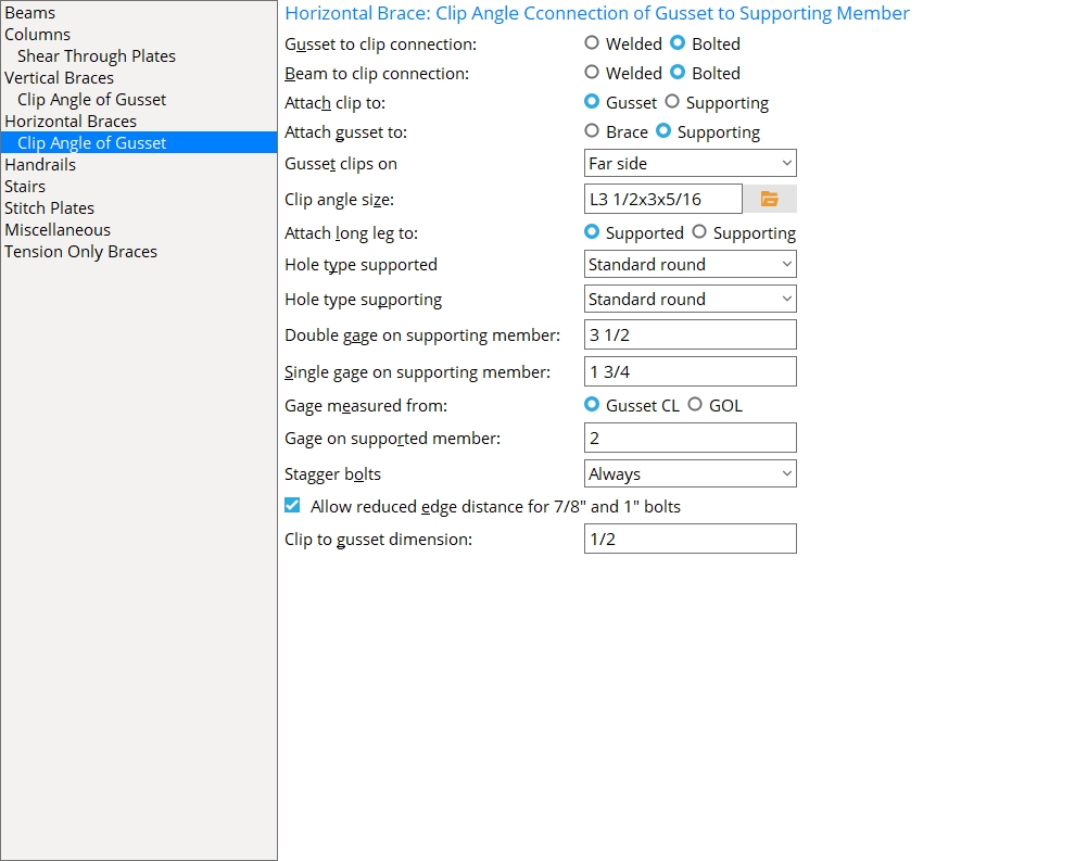
Horizontal Braces: Clip angle Connection of Gusset to Supporting Member
Gusset to clip connection: ![]() Welded or
Welded or ![]() Bolted. This applies when Gusset to clip connection is set to Automatic under
Bolted. This applies when Gusset to clip connection is set to Automatic under ![]() Connection specifications
Connection specifications
|
||
| For a gusset to two beams, the gusset-to-brace connection is shop bolted. and the clip-to-beam connection is field bolted. The gusset-to-clip connection is Welded or Bolted per the choice made here. |
Beam to clip connection: Welded or Bolted. This applies when Beam to clip connection is set to Automatic under ![]() Connection specifications
Connection specifications
|
||||||
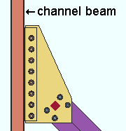
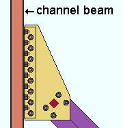
| In these examples, Attach clip to and Attach gusset to are each set to On supporting, which means the clip angle and gusset assembly shop attaches to the beam. The clip angle shop welds or bolts to the back of the channel beam. |
Welded instructs connection design to shop weld the horizontal brace gusset clip to the supporting beam.
Bolted instructs connection design to bolt the horizontal brace gusset clip to supporting beam.
Attach clip to: Automatic or On gusset or On supporting. This applies when Attach clip to is set to Automatic under ![]() Connection specifications
Connection specifications
|
||||||
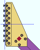
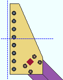
| In both of these examples, Attach gusset to is set to On brace. The beam in these screen shots is hidden (displayed in Stick with Display Options > Member lines turned off). |
On gusset specifies that the gusset clip angle(s) shop bolt or shop weld to the gusset plate.
On supporting specifies that the gusset clip angle(s) shop bolt or shop weld to the beam. The clip angle will be shipped with the beam and detailed on the beam. Clip angles must be shop welded to an HSS/TS beam and can optionally be shop welded to a channel beam.
Attach gusset to: Automatic or On brace or On supporting. This applies when Attach gusset to is set to Automatic under ![]() Connection specifications
Connection specifications
|
||||||
| In both of these examples, Attach clip to is set to On brace. The beam in these screen shots is hidden (displayed in Stick with Display Options > Member lines turned off). |
On brace specifies that the gusset shop bolt to the brace. The gusset plate will be shown on the horizontal brace detail. Gusset clip angles may or may not be shop attached to (and shipped with) the gusset plate potentially depending on the choice made to Attach clip to.
On supporting specifies that the entire gusset-plate-and-clip-angle assembly be shop attached to and shipped with the beam and shown on the beam detail. The clip angle may shop bolt or shop weld to the beam. Clip angles can be shop welded to an HSS/TS or channel beam. Clip angles cannot be shop bolted to an HSS/TS beam.
Gusset clips on: Both sides or Near side or Far side. This Horizontal Braces section option applies when Gusset clips on is set to Automatic under ![]() Connection specifications
Connection specifications
|
Both sides attaches the clip angles to both the near and far sides of the gusset plate. Connection design may create clip angles on one side of the gusset to prevent interference with the top/bottom flange of the supporting beam. |
|
Near side instructs connection design to try to place the clip angles on the near side (top) of the gusset. If the clip angles clash with the beam, connection design moves them to the far side instead of failing the connection. |
|
Far side instructs connection design to try to place the clip angles on the far side (bottom) of the gusset. If the clip angles clash with the beam, connection design moves them to the near side instead of failing the connection. |
Clip angle size: The section size of the angle material to be used when Clip angle size is set to Automatic under ![]() Connection specifications
Connection specifications
The angle you enter here must exist in the local shape file, or validation does not accept your entry. To enter an angle section size, you can type in the section size that you want, or you can press the file cabinet browse button
( and double-click any section that is on the list of available angles in the local shape file.
Attach long leg to: ![]() Supported or
Supported or ![]() Supporting. This Horizontal Braces section option applies when Automatic is selected for Attach long leg to under
Supporting. This Horizontal Braces section option applies when Automatic is selected for Attach long leg to under ![]() Connection specifications
Connection specifications
|
The supported is the gusset plate. The supporting is the web of the beam. |
Hole type supported: Standard round or Short slot or Long slot or Oversized or User slot #1 or User slot #2. This is the hole type for shop bolting the leg of the clip angle to the horizontal brace gusset plate when Hole type supported is set to ![]() Auto
Auto
Hole type supporting: Standard round or Short slot or Long slot or Oversized or User slot #1 or User slot #2. This is the hole type for field bolting the outstanding leg of the clip angle to the supporting beam when Hole type supporting is set to ![]() Auto
Auto
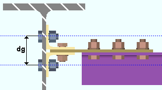
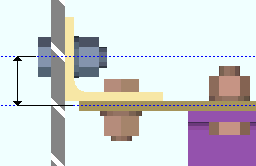
Double gage on supporting member: The center-to-center distance between the columns of holes in the outstanding legs of the near side and far side clip angles on the horizontal brace gusset plate.
|
dg = double gage on supporting member |
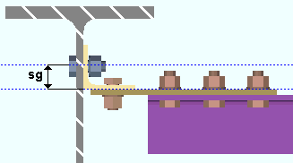
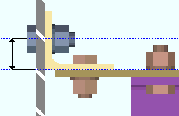
Single gage on supporting member: The distance from where the Gage is measured from to the first column of holes in the leg that fastens to the supporting beam.
|
sg = single gage on supporting member |
Gage measured from: ![]() Gusset CL or
Gusset CL or ![]() GOL.
GOL.
|
|
Gage on supported member: The distance from the face of the outstanding leg of the clip angle to the first column of holes in the leg that fastens to the gusset plate.
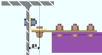
|
ga = gage on supported member |
Stagger bolts: ![]() or
or ![]() . This Horizontal Braces section option applies when Automatic is selected for Stagger bolts under
. This Horizontal Braces section option applies when Automatic is selected for Stagger bolts under ![]() Connection specifications
Connection specifications
 |
 |
If this box is checked (
If the box is not checked (
Allow reduced edge distance for 7/8" and 1" bolts: ![]() or
or ![]() . For metric bolts, this applies to bolts with diameters of 20 mm, 22 mm and 24 mm. This applies to clip angles for attaching the gusset of a horizontal brace to a beam.
. For metric bolts, this applies to bolts with diameters of 20 mm, 22 mm and 24 mm. This applies to clip angles for attaching the gusset of a horizontal brace to a beam.
|
v = edge distance |
If this box is checked (
If the box is not checked (
Also: Bolt diameter sets the diameter of bolts for horizontal brace gusset clips.
Clip to gusset dimension: The distance from the web of the supporting beam to the edge of the horizontal brace gusset plate. This applies to horizontal brace gusset plates that bolt to a beam web with a clip angle.
|
d = clip to gusset dimension |
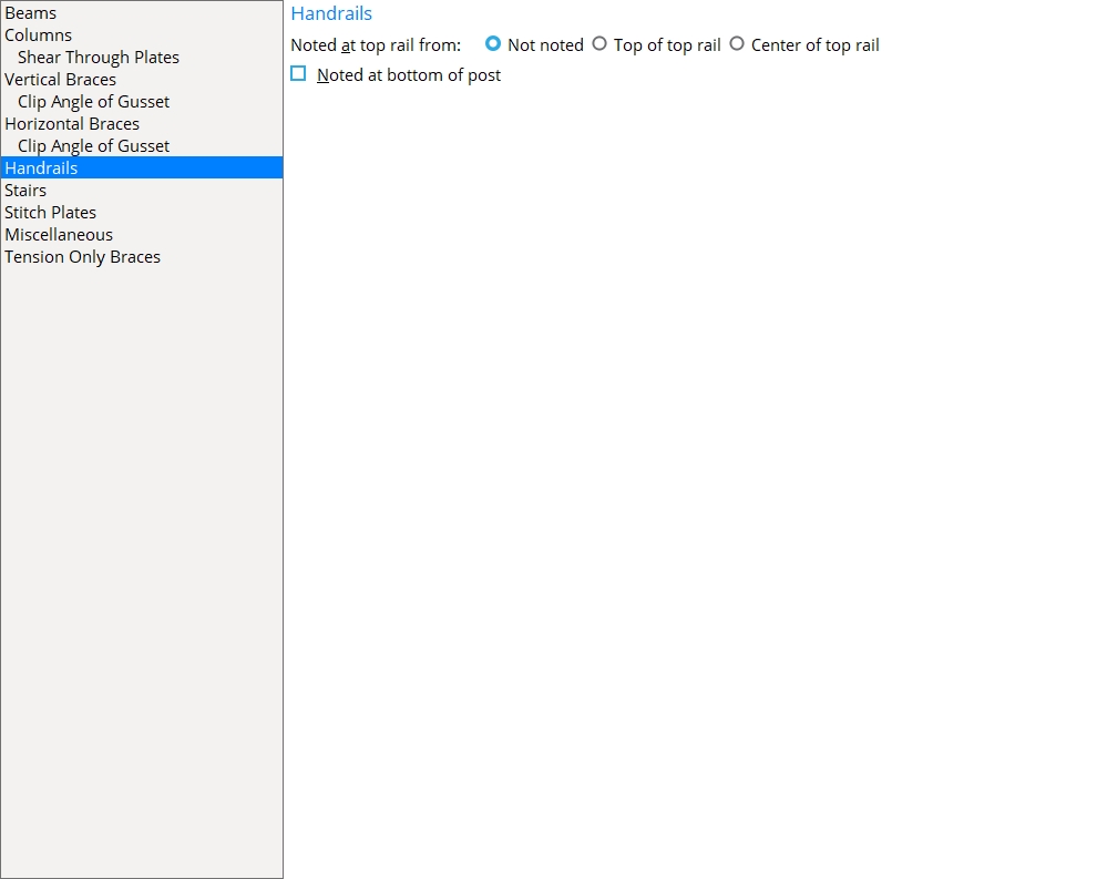
Handrails
Noted at top rail from: ![]() Not noted or
Not noted or ![]() Top of top rail or
Top of top rail or ![]() Center of top rail. This Handrail section option applies to the detail of any handrail that you select when you Detail Members.
Center of top rail. This Handrail section option applies to the detail of any handrail that you select when you Detail Members.
|
|
|
Noted at bottom of post: ![]() or
or ![]() . This Handrail section option applies to the detail of any handrail that you select when you Detail Members.
. This Handrail section option applies to the detail of any handrail that you select when you Detail Members.
 |
 |
If this box is checked (
If the box is not checked (
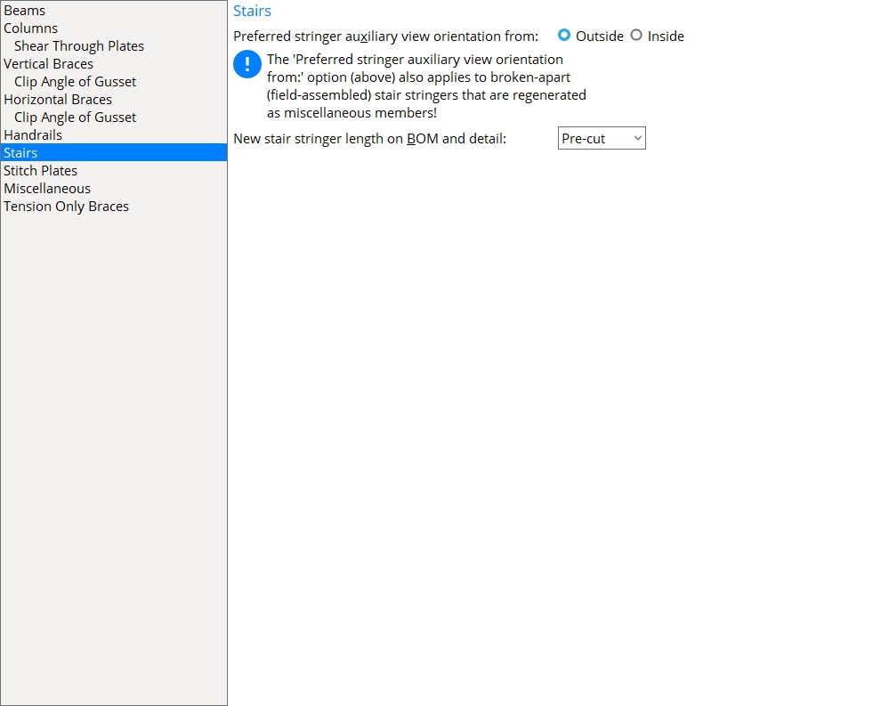
Stairs
Preferred stringer auxiliary view orientation from: ![]() Outside (default) or
Outside (default) or ![]() Inside. This affects Member Isolation and Detail Members.
Inside. This affects Member Isolation and Detail Members.
|
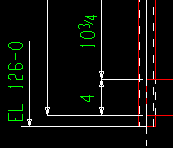
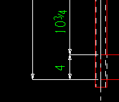
New stair stringer length on BOM and detail: Pre-cut or Post-cut. This Stairs section option applies when the End condition for a stair stringer is Bolt to floor. It sets the default selection that is made for NS/FS stringer length on BOM on the Stair Edit window. This affects the description x length callout in the submaterial detail as well as the Length reported in the member bill of material.
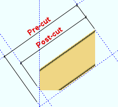
Example: A short stair with a bolt-to-floor end condition.
Pre-cut Post-cut 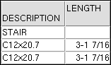

Pre-cut results in the Length reported for the near side and far side stringers in a stair's bill of material being the Order length of that material. The pre-cut length will also be reported, along with the description, in the callout on a subsequently auto detailed submaterial detail of the stringer. The "pre-cut length" corresponds to what is referred to as the saw length on the CNC Setup window. This is the length of the stringer material before cuts were made to its end so that it could be bolted to the floor.
Post-cut results in the stringer's Length in the bill being its Part length.The description and pre-cut length will also be reported in the callout on the submaterial detail. For CNC, the post-cut length is referred to as the final length. This is the length of the stringer material after its end was cut so that it could be bolted to the floor.
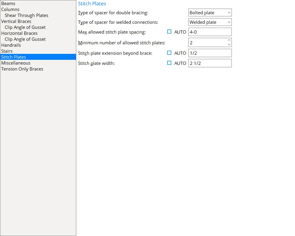
Stitch Plates
Type of spacer for double bracing: Bolted ring or Bolted plate or Welded plate. This sets the type of spacer to be used for angle or channel Double material vertical bracing or angle Double material horizontal bracing. On double-angle horizontal braces, either Both sides must be selected or the Stitch plate gap must be greater than zero. Spacers are generated even if the Input connection type is Plain end on both ends of the brace. However, if the connections fail on both ends of the brace, you do not get stitch plates.
Bolted ring
|
Bolted plate
|
Welded plate

|
Bolted ring causes a bolted round bar to be used as the spacer for a Back to back double-angle or double-channel vertical brace or a double-angle horizontal brace on Both sides of the gusset (or whose Stitch plate gap is greater than zero). For a Star configuration vertical brace, a bolted plate stitch plate is used.
Bolted plate causes a bolted rectangular plate to be used as the spacer. As with a bolted ring, holes are generated through the plate and both materials of the
Welded plate causes a simple rectangular plate (without holes or bolts) to be used as the spacer between the two materials that make up the vertical brace or horizontal brace.
Also: Stitch plate extension beyond brace and Stitch plate width give you control over the size of stitch plates.You can set the stitch plate steel grade in Home > Project Settings > Fabricator > Standard Fabricator Connections > Preferred Connection Material Sizes > Preferred Plate Sizes > Other Plates.
Type of spacer for welded connections: Bolted ring or Bolted plate or Welded plate. This Sitch Plates section option applies to the design of welded back-to-back double-angle vertical bracing to the stem of a W tee (click here for an example).
Bolted ring
|
Bolted plate
|
Welded plate
|
| The members in these screen shots are displayed in solid transparent main so that you can see the spacers. | ||
Bolted ring shop bolts the two angles together using a round bar with a hole in it as the spacer (stitch plate).
Bolted plate shop bolts the two angles together using a rectangular plate with a hole in it as the spacer (stitch plate).
Welded plate causes a simple rectangular plate (without holes or bolts) to be used as the spacer (stitch plate) between the two angles that make up the double-angle vertical brace.
Also: Stitch plate extension beyond brace and Stitch plate width control the size of stitch plates. The stitch plates shown above are what you get when both of these options are checked.
Max allowed stitch plate spacing: ![]() or
or ![]() . This distance sets the default spacing (center-to-center) between stitch plates and theleft/right end of the brace. Left/right end = end of the brace material for a Plain end or Welded connection. Left/right end = inside bolt if the end has a gusset.
. This distance sets the default spacing (center-to-center) between stitch plates and theleft/right end of the brace. Left/right end = end of the brace material for a Plain end or Welded connection. Left/right end = inside bolt if the end has a gusset.
|
s = spacing |
If this box is checked (
If the box is not checked (
To apply this setting: For the spacing and/or number of stitch plates set here to apply to the design of stitch plates,
Minimum number of allowed stitch plates: This number (1 or 2 or 3 ...) applies to vertical braces and horizontal braces with stitch plates. It sets the default minimum number of stitch plates that will be generated, regardless of the Max allowed stitch plate spacing.
Number of stitch plates = 3 To apply this setting: For the spacing and/or number of stitch plates set here to apply to the design of stitch plates,
needs to be checked for Max stitch plate spacing and Number of stitch plates on the Vertical Brace Edit window (or for Max stitch plate spacing and Number of stitch plates on the Horizontal Brace Edit window).
Stitch plate extension beyond brace: ![]() or
or ![]() . This Sitch Plates section option applies no matter what Type of spacer is selected. It applies to both horizontal and vertical braces.
. This Sitch Plates section option applies no matter what Type of spacer is selected. It applies to both horizontal and vertical braces.
X = extension beyond brace
 |
If this box is checked (
If the box is not checked (
Stitch plate width: ![]() or
or ![]() . This Sitch Plates section option applies no matter what Type of spacer is selected. It applies to both horizontal and vertical braces.
. This Sitch Plates section option applies no matter what Type of spacer is selected. It applies to both horizontal and vertical braces.
W = width of stitch plate
 |
If this box is checked (
If the box is not checked (
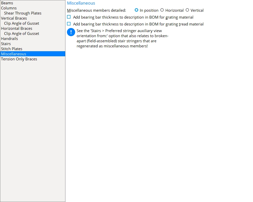
Miscellaneous
Miscellaneous members detailed: ![]() In position or
In position or ![]() Horizontal or
Horizontal or ![]() Vertical. This Miscellaneous section option applies to legacy miscellaneous members when you Detail Members. It does not apply to the new miscellaneous members, which are custom members.
Vertical. This Miscellaneous section option applies to legacy miscellaneous members when you Detail Members. It does not apply to the new miscellaneous members, which are custom members.
(not shortened) 
|
(shortened) 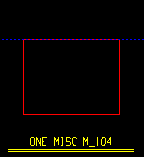
|
(shortened) 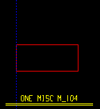
|
To add member views to details: Member Isolation
Altering a member's main view: In Member Isolation
A quick way to alter a main view: Rotate View in Member Isolation
Add bearing bar thickness to description in BOM for grating material: ![]() or
or ![]() . This applies to both miscellaneous members and legacy miscellaneous members.
. This applies to both miscellaneous members and legacy miscellaneous members.
|
|
If this box is checked (
If the box is not checked (
Add bearing bar thickness to description in BOM for grating tread material: ![]() or
or ![]() . This applies to both miscellaneous members and legacy miscellaneous members.
. This applies to both miscellaneous members and legacy miscellaneous members.
|
|
If this box is checked (
If the box is not checked (
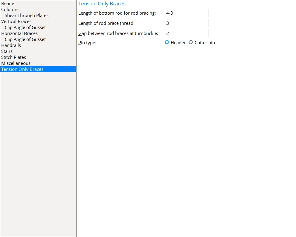
Tension Only Braces
Length of bottom rod for rod bracing: A distance. This sets the default for the Rod length and Middle rod length locks in the leaf named ![]() Brace Connection To Gusset
Brace Connection To Gusset
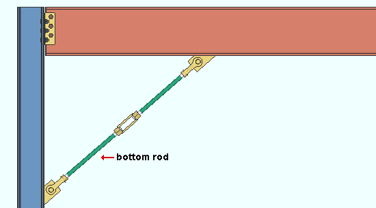
Connection design lock (bottom rod): Rod length
Connection design lock (top rod): Rod length
Connection design lock (middle rod): Middle rod length
Round bar material: Material length (makes the connection graphical)
Connection Guide: Rod Bracing.
Length of rod brace thread: A distance. This sets the default for the Thread length lock in the leaf named ![]() Brace Connection To Gusset
Brace Connection To Gusset
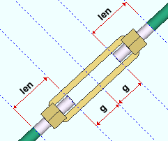
|
len = length of rod brace thread |
Connection design lock (all rods): Thread length
Round bar material (left or right end of a rod): Thread length (makes the connection graphical)
Gap between rod braces at turnbuckle: The distance from the end of the rod brace to the center of the turnbuckle. This distance is half the distance between the two round bars that are joined at a turnbuckle to form a rod brace.
|
|
g = gap between rode braces at turnbuckle |
.
Connection design locks (bottom rod): Clevis pin shoulder height & Clevis pin head thickness
Connection design locks (top and middle rods): Clevis pin shoulder height & Clevis pin head thickness
Clevis material: Pin head thickness & Pin head diameter (make the connection graphical)
-
If you have made certain changes to this screen after adding members to the 3D model, you should interactively mark for processing (or Process Selected) all members in your current Job, then Process and Create Solids in order to ensure design consistency throughout the Job.
-
Settings applied to the Member Detailing Settings screen are for your current Fabricator. A different set of settings will apply when you Change Fabricator.
- Red or yellow exclamation point icons
 or
or 

